
TM 5-3805-255-14
0093
REMOVAL CONTINUED
4. Crank engine until connecting rod to be removed (Figure 3, Item 1) is at its lowest position.
NOTE
Mark pistons, connecting rods and connecting rod bearing caps so that they can be
installed in same cylinders from which they were removed, and in same position.
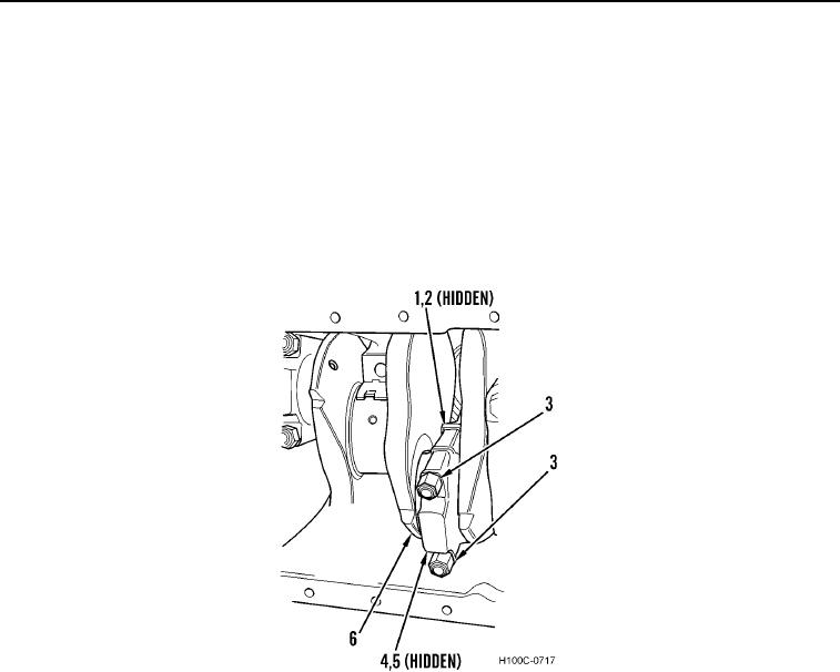
5. Remove two elastic stop safety nuts (Figure 3, Item 3) and bearing cap (Figure 3, Item 4) from crankshaft
(Figure 3, Item 6). Tap cap lightly with a mallet if necessary to aid removal. Lower bearing insert (Figure 3, Item
5) is removed with bearing cap (Figure 3, Item 4). Upper half of bearing (Figure 3, Item 2) will remain on
connecting rod (Figure 3, Item 1). Discard two elastic stop safety nuts.
Figure 3. Connecting Rod Cap Removal.
0093
0093-4