
TM 5-3805-255-14
0093
CLEANING AND INSPECTION
00093
Piston Pin Bushing Replacement
00093
1. Replace connecting rod bushings using bushing removal and installing tool, PLT-544-1 which consists of Items
1, 3, 4, 5, 6, and 7 shown in Figure 8.
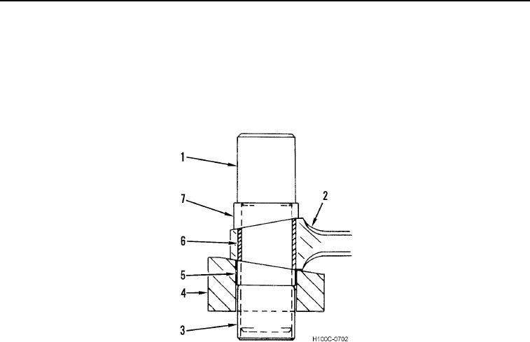
2. A center line is scribed on block (Figure 6, Item 4) and sleeves (Figure 6, Item 7) to ensure locating correct
position of bushing (Figure 6, Item 6) on connecting rod (Figure 6, Item 2).
Figure 6. Connecting Rod Bushing Removal and Installation Tools.
0093
0093-7