
TM 5-3805-255-14
0093
CLEANING AND INSPECTION CONTINUED
00093
NOTE
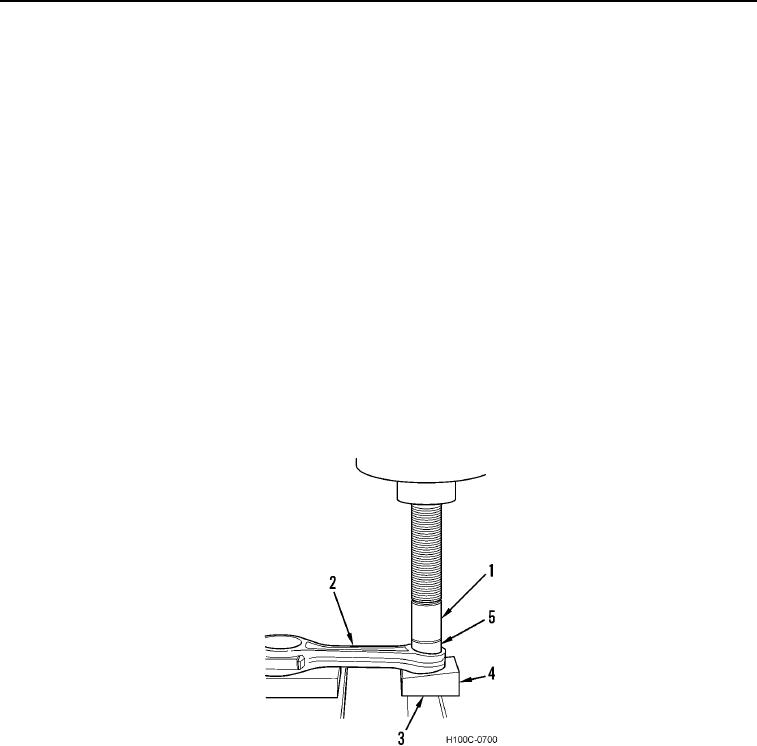
For clarity, these items are numbered the same in Figures 8, 9, 10, and 11:
1
Mandrel
2
Connecting Rod
3
Guide Sleeve
4
Block
5
Removing Sleeve
6
Bushing
7
Sleeve
3. Remove old bushing as follows:
a. Using a suitable arbor press, position connecting rod (Figure 7, Item 2) on block (Figure 7, Item 4).
b. Assemble removing sleeve (Figure 7, Item 5) on mandrel (Figure 7, Item 1). Place assembled tool on
connecting rod (Figure 7, Item 2), indexing center line mark on removing sleeve with center line mark on
block (Figure 7, Item 4). Place guide sleeve (Figure 7, Item 3) on lower end of mandrel in block to act as a
guide. This will also center connecting rod bushing with hole in block.
c.
Press bushing until halfway removed.
Figure 7. Removing Bushing (First Step).
0093
0093-8