
TM 5-3805-255-14
0095
VALVE RECONDITIONING CONTINUED
Insert Installation
00095
NOTE
Valve seat inserts which are not fitted tight work loose, permitting carbon formations to
collect on outer surface of insert, thus insulating exhaust heat within insert, preventing
proper heat dissipation through cylinder head.
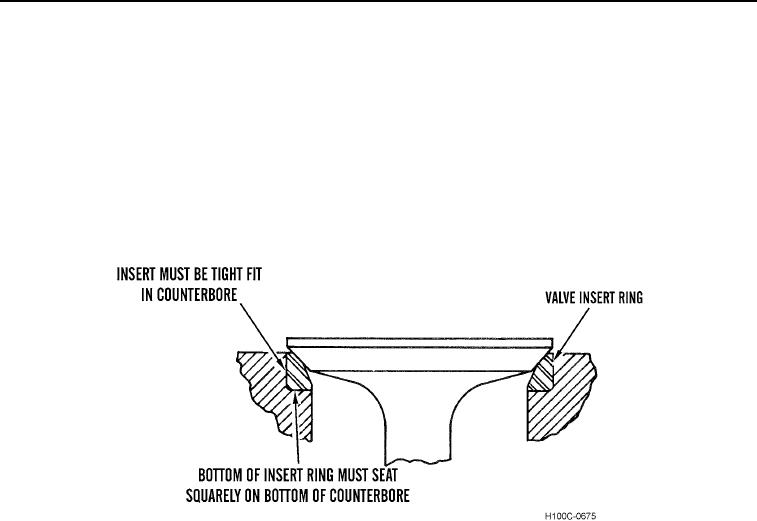
1. To assure maximum valve and insert life, it is essential that valve insert ring be installed to obtain maximum
contact with bottom and sides of ring counterbore as shown in Figure 16. Proper heat dissipation through valve
insert ring can only be accomplished by valve insert ring being a tight fit in cylinder head with bottom of insert
ring squarely seated on bottom of counterbore.
Figure 16. Insert Ring Properly Installed.
0095
0095-15