
TM 5-3805-255-14
0095
VALVE RECONDITIONING CONTINUED
NOTE
Valve guides have a 30 chamfer at top of guide, and an internal thread in bottom portion.
Guides must be installed with threaded end downward.
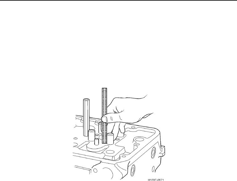
4. Use a mandrel to press new valve guides in from top of cylinder head. Guides must extend specified distance
above top surface of cylinder head (Figure 12) (see Intake and Exhaust Valve Specifications in this work
package).
5. All guides furnished as service parts are reamed to size. However, as they are installed, remove any possible
burrs or slight distortion caused by pressing operation (see Intake and Exhaust Valve Specifications in this
work package)
Figure 12. Measuring Position of Valve Guides.
0095
0095-10