TM 5-3805-255-14
0095
VALVE RECONDITIONING CONTINUED
Valve Bridge and Guides
00095
1. Measure ID of bridge guides in same manner as valve guides. Measure OD of valve bridge stems across
greater diameter (not flat sides) with a micrometer. If difference between these two reading is greater than
maximum allowable stem clearance (see Intake and Exhaust Valve Specifications in this work package),
replace bridge stems and guides.
2. All replacement guides now have an outside diameter of 0.6870 to 0.6875 in. (17.488 to 17.501 mm). If not, it
must be enlarged to this dimension by reaming to a depth of 0.720 in. (18.29 mm) and restoring original
chamfer to edge of hole. New guide will then have a press fit of 0.001 to 0.002 in. (0.03 to 0.05 mm). It is
recommended that new guides be installed with a press and a suitable sleeve driver.
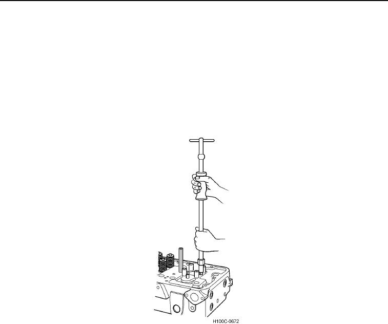
Figure 13. Removing Valve Bridge Guides.
0095
0095-11

