TM 5-3805-255-14
0095
VALVE RECONDITIONING CONTINUED
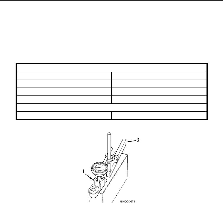
3. This method is recommended for checking wear on valve lever bridge (Figure 14, Item 1). Other methods can
be used. Using a block of hard wood with one side finished, drill a hole large enough to allow stem of bridge to
fit through. If a surface plate is available, use that with suitable supports instead of block of hard wood.
4. Install indicator into indicator block (Figure 14, Item 2) and place block on hard finished surface. Place indicator
point on bridge at edge of wear groove. Set indicator at zero and move indicator block until indicator point
drops into wear groove. Take a reading. If reading exceeds wear limit, replace valve bridge.
Table 1. Wear Limits.
Valve Lever Bridge and Bridge Guide
Guide Length
2.31 in. (56.7 mm)
Guide Inside Diameter
0.5015 to 0.5025 in. (12.738 to 12.754 mm)
Maximum Permissible Guide Inside Diameter
0.5045 in. (12.81mm)
Bridge Stem Clearance in Guide
0.0015 to 0.0035 in. (0.38 to 0.089 mm)
Maximum Permissible Valve Lever Bridge Wear
Wear at Valve Lever Contact Surface
0.004 in. (0.10 mm)
Figure 14. Checking Valve Bridge for Wear.
0095
Valve Seats and Seat Inserts
00095
1. Inspect intake and exhaust valve faces and seat inserts for cracks and burned condition. Also check valve seat
inserts for looseness.
2. Remove defective valve seat inserts with an insert puller.
3. If new oversize valve seat inserts are installed, ream insert counterbore in cylinder head to dimension shown in
Table 1 to obtain correct fit.
0095-12

