
TM 5-3805-255-14
0097
REMOVAL CONTINUED
CAUTION
After camshaft gear is removed, DO NOT ROTATE crankshaft without first backing off all
valve lever adjusting screws. This is to relieve valve levers in order to seat all valves and
avoid damage by piston up-strokes. Failure to follow these instructions may result in
damage to equipment.
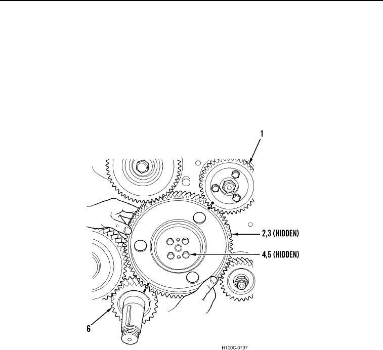
7. Crank engine until timing marks on crankshaft gear (Figure 4, Item 6), camshaft gear (Figure 4, Item 2), and
injection pump drive gear (Figure 4, Item 1) are aligned. Remove four bolts (Figure 4, Item 4), washers (or
lockplate) (Figure 4, Item 5), and camshaft gear from camshaft (Figure 4, Item 3).
Figure 4. Removing Camshaft Gear.
0097
0097-5