
TM 5-3805-255-14
0097
REMOVAL CONTINUED
NOTE
Fan drive idler gear shaft bolt has a left-hand thread.
If fan drive idler gear shaft is to be removed, mark one locating dowel and shaft casting
next to dowel. This will ensure correct installation of shaft upon assembly.
12. Remove fan drive idler gear shaft bolt and bearing retainer. Remove gear and bearing in same manner as
hydraulic pump idler gear.
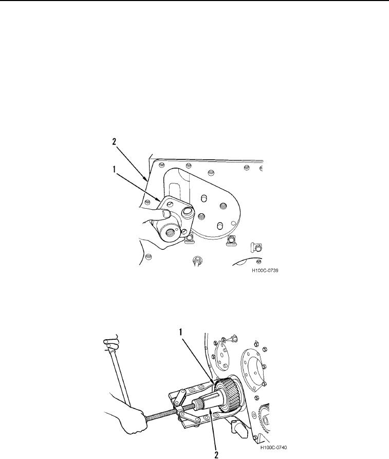
13. Remove bolt and fan drive idler gear shaft (Figure 6, Item 1) from crankcase (Figure 6, Item 2) and remove
shaft.
Figure 6. Removing Fan Drive Idler Gear Shaft.
0097
14. Remove crankshaft gear (Figure 7, Item 1) from crankshaft (Figure 7, Item 2).
Figure 7. Removing Crankshaft Gear.
0097
0097-7