
TM 5-3805-255-14
0097
REMOVAL CONTINUED
15. Remove injection pump drive gear with gear hub attached.
16. Remove nut from shaft and lube oil and water pump drive gear.
17. If crankcase front plate is to be removed proceed as follows:
a. Disconnect all lines to fuel injection pump. Remove two bolts, nuts, and washers securing injection pump
to mounting block. Remove adapter housing with fuel injection pump attached (WP 0100).
b. Remove lube oil and water pump (WP 0023).
c.
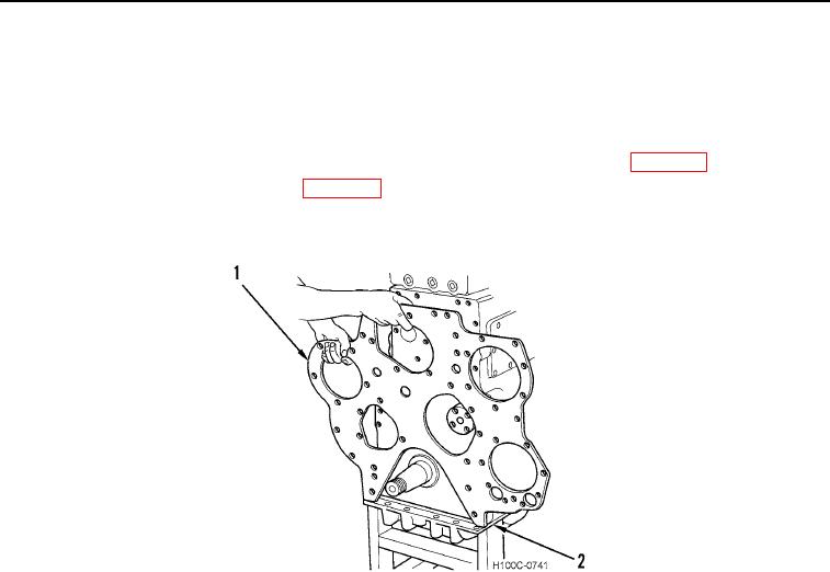
Remove bolts, lock and front plate (Figure 8, Item 1) from crankcase (Figure 8, Item 2).
Figure 8. Removing Crankcase Front Plate.
0097
END OF TASK
0097-8