TM 5-3805-255-14
0098
ASSEMBLY CONTINUED
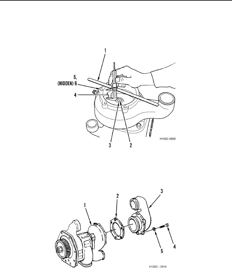
16. Install impeller (Figure 26, Item 3) onto drive shaft (Figure 26, Item 2) to a depth of 1.445 to 1.465 in. (36.70 to
37.21 mm). Using a caliper gauge and a straightedge, measure from water pump housing rear face (Figure 26,
Item 5) to machined surface on impeller.
17. Rotate pump drive gear (Figure 26, Item 6). If impeller (Figure 26, Item 3) is rubbing on water pump housing
(Figure 26, Item 5), recheck position of impeller as described in step 15.
Figure 26. Water Pump Impeller-to-Housing Clearance.
0098
18. Install new water pump inlet elbow gasket (Figure 27, Item 2) and water pump inlet elbow (Figure 27, Item 3)
on water pump housing (Figure 27, Item 1).
19. Install six washers (Figure 27, Item 5) and bolts (Figure 27, Item 4) on water pump housing (Figure 27, Item 1).
Tighten bolts to 38 lb-ft (52 Nm).
Figure 27. Water Pump Housing Assembly.
0098
END OF TASK
END OF WORK PACKAGE
0098-21/(22 blank)

