
TM 5-3805-255-14
0098
CLEANING AND INSPECTION CONTINUED
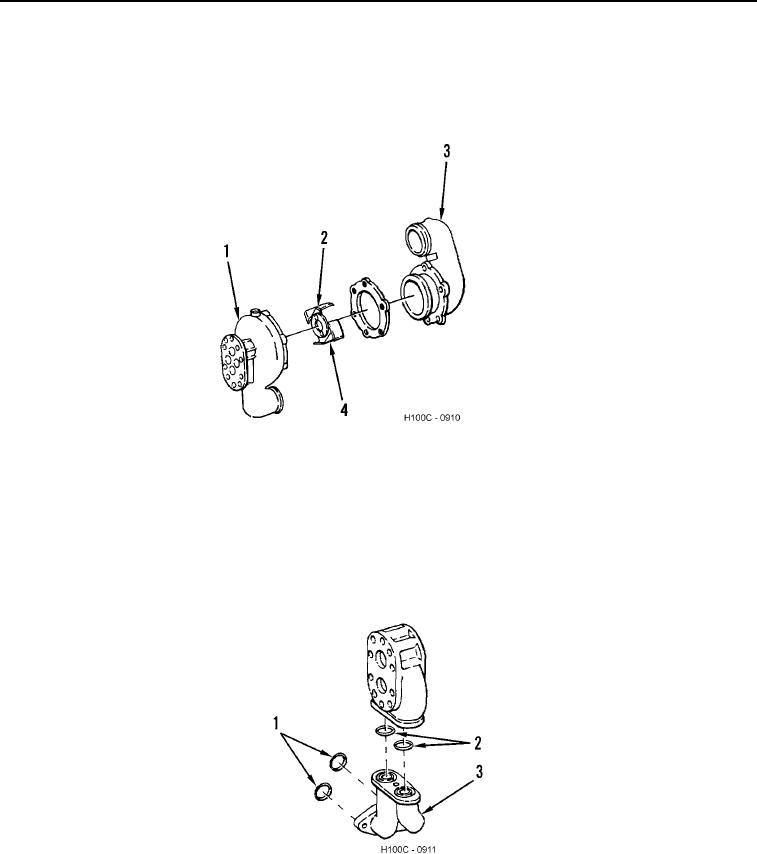
9. Examine water pump impeller (Figure 18, Item 2) and water pump housing (Figure 18, Items 1 and 3) contact
surfaces for evidence of wear or grooving. Replace if necessary.
10. Inspect four impeller vanes (Figure 18, Item 4) and remove any nicks, burrs, or roughness.
Figure 18. Water Pump Impeller Inspection.
0098
11. Inspect oil scavenging pump manifold (Figure 19, Item 3) (if equipped). Remove two O-rings (Figure 19,
Item 2). Discard O-rings.
12. If oil scavenging pump manifold (Figure 19, Item 3) is removed from engine, remove manifold-to-engine O-
rings (Figure 19, Item 1). Discard O-rings.
13. It is also recommended that oil pan be removed and oil pick-up tube be pressure checked for leaks.
Figure 19. Scavenge Oil Pump Manifold and O-Rings.
0098
END OF TASK
0098-16