TM 5-3805-255-14
0100
DISASSEMBLY
000100
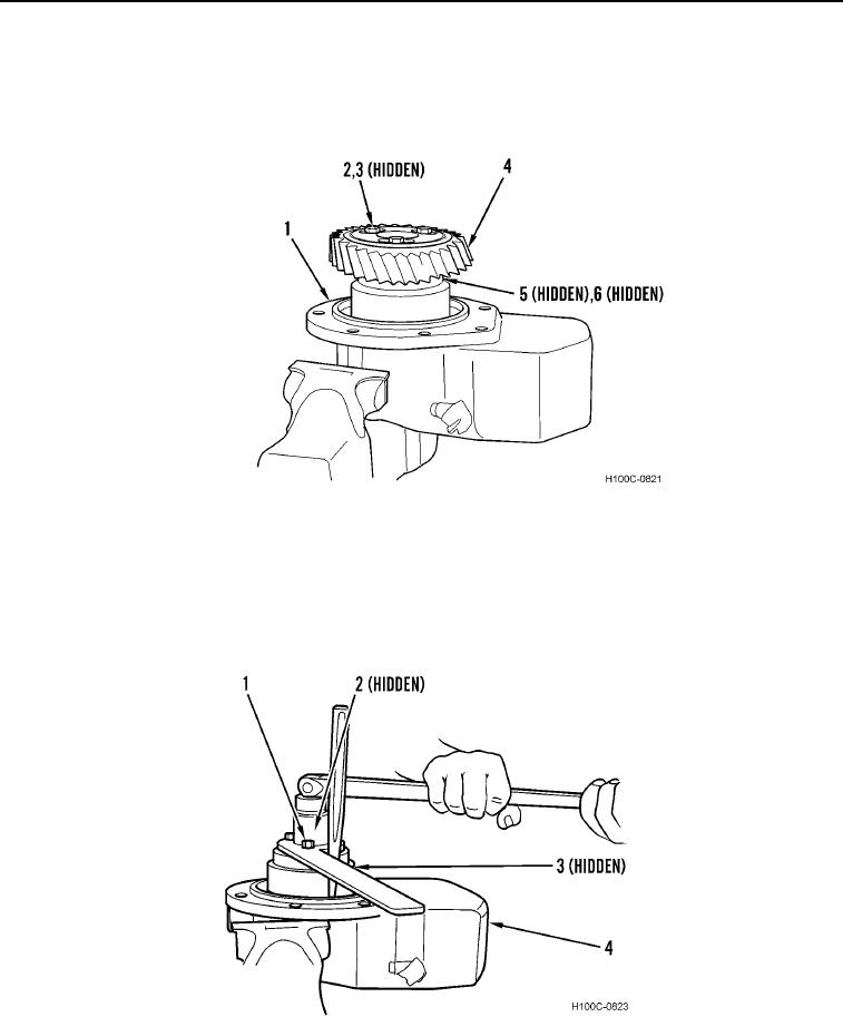
1. Secure adapter housing (Figure 2, Item 1) in a vise with soft jaws.
2. Remove three bolts (Figure 2, Item 2), washers (Figure 2, Item 3), two plates (Figure 2, Item 6), and gear
(Figure 2, Item 4) from pinion shaft (Figure 2, Item 5).
Figure 2. Removing Drive Gear.
0100
3. Secure injection pump hub holding tool to hub (Figure 3, Item 3) with two bolts (Figure 3, Item 1).
4. Install a suitable drift into hole in adapter housing (Figure 3, Item 4) to anchor holding tool.
5. Remove nut (Figure 3, Item 2) from pinion shaft (Figure 3, Item 3).
6. Remove drift, two bolts (Figure 3, Item 1), and holding tool from pinion shaft (Figure 3, Item 3).
Figure 3. Pinion Shaft Nut Removal.
0100
0100-3

