
TM 5-3805-255-14
0098
ASSEMBLY
00098
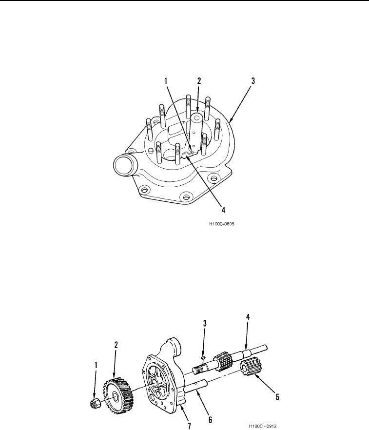
1. Position idler shaft (Figure 20, Item 2) in oil pump body (Figure 20, Item 3) so that oil holes (Figure 20, Item 1)
in shaft are in line with oil slot (Figure 20, Item 4) in pump body.
2. Install idler shaft (Figure 20, Item 2) into body (Figure 20, Item 3) until lower oil hole (Figure 20, Item 1) in shaft
is indexed with slot (Figure 20, Item 4) as shown.
Figure 20. Idler Shaft Installation.
0098
3. Install drive shaft with body gear (Figure 21, Item 4) into oil pump body (Figure 21, Item 7).
4. Install Woodruff key (Figure 21, Item 3) on drive shaft (Figure 21, Item 4) and install drive gear (Figure 21, Item
2) onto shaft. Install drive gear nut (Figure 21, Item 1) and torque to 140 lb-ft (190 Nm).
5. Install idler gear with bushings (Figure 21, Item 5) on idler shaft (Figure 21, Item 6) so that marks on two gears
line up.
Figure 21. Oil Pump Assembly.
0098
0098-17