
TM 5-3805-255-14
0100
DISASSEMBLY CONTINUED
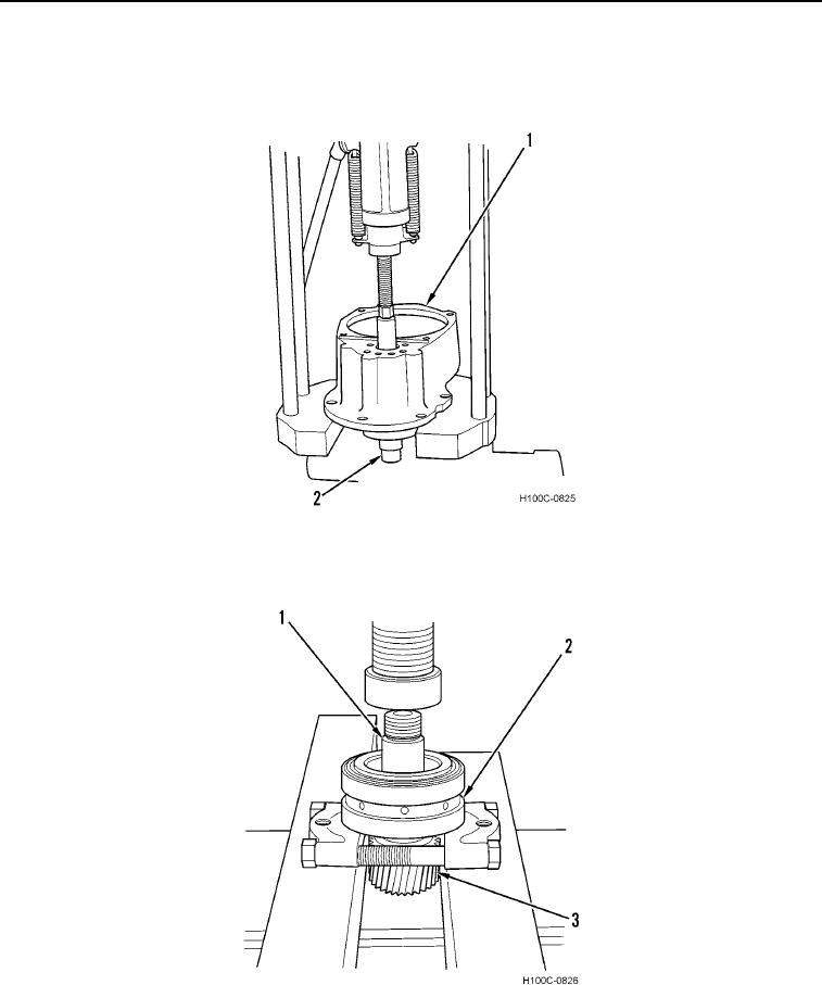
10. Remove adapter housing (Figure 5, Item 1) from vise and position on a press.
11. Remove pinion shaft with bearing (Figure 5, Item 2) from adapter housing (Figure 5, Item 1).
Figure 5. Pinion Shaft and Bearing Removal.
0100
12. Support bearing cone (Figure 6, Item 2) and remove shaft (Figure 6, Item 1) from gear (Figure 6, Item 3).
Figure 6. Bearing Removal.
0100
END OF TASK
0100-5