TM 5-3805-255-14
0103
ASSEMBLY CONTINUED
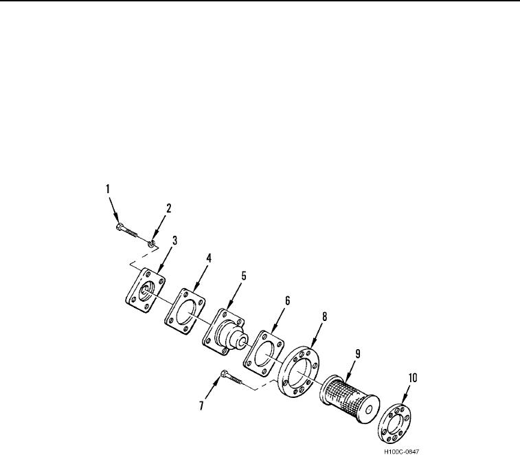
3. Install gasket retainer (Figure 36, Item 10), filter (Figure 36, Item 9), filter retainer (Figure 36, Item 8), and four
bolts (Figure 36, Item 7) on transmission cover.
NOTE
Check valve should allow fluid flow in only one direction. Install new check valve if fluid
flows in both directions.
4. Install new gasket (Figure 36, Item 6), check valve (Figure 36, Item 5), new gasket (Figure 36, Item 4), flange
(Figure 36, Item 3), four new lockwashers (Figure 36, Item 2), and bolts (Figure 36, Item 1) on transmission
cover.
Figure 36. Filter Assembly.
0103
0103-23

