
TM 5-3805-255-14
0103
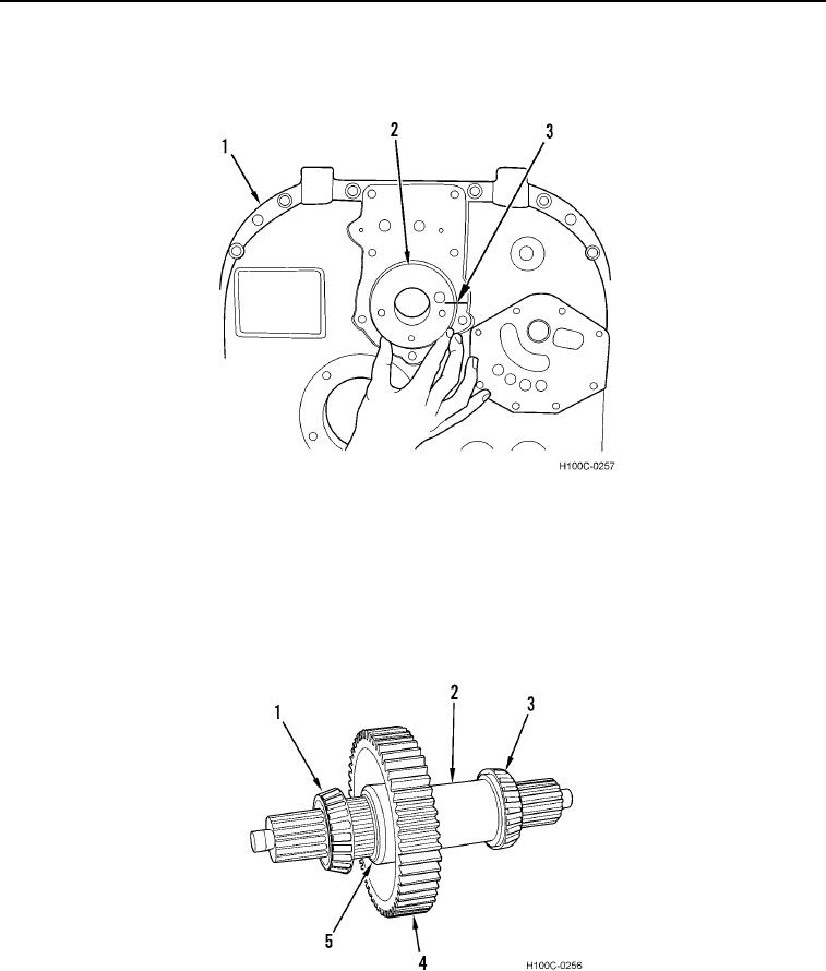
ASSEMBLY CONTINUED
9. Align identification marks (Figure 40, Item 3) on oil supply cover (Figure 40, Item 2) with front cover (Figure 40,
Item 1). Install oil supply cover in base of front cover.
Figure 40. Oil Supply Cover Installation.
0103
NOTE
Coat shaft with Molykote or equivalent lubricant prior to installation of gear and bearing.
It may be necessary to heat bearing prior to installation.
10. Install gear (Figure 41, Item 4), snap ring (Figure 41, Item 5), and bearings (Figure 41, Items 1 and 3) on shaft
(Figure 41, Item 2).
Figure 41. Output Shaft Assembly.
0103
0103-27