
TM 5-3805-255-14
0103
ASSEMBLY CONTINUED
CAUTION
Shaft must be assembled into chamfered side of gear. Incorrect installation will result in
gear and shaft failure.
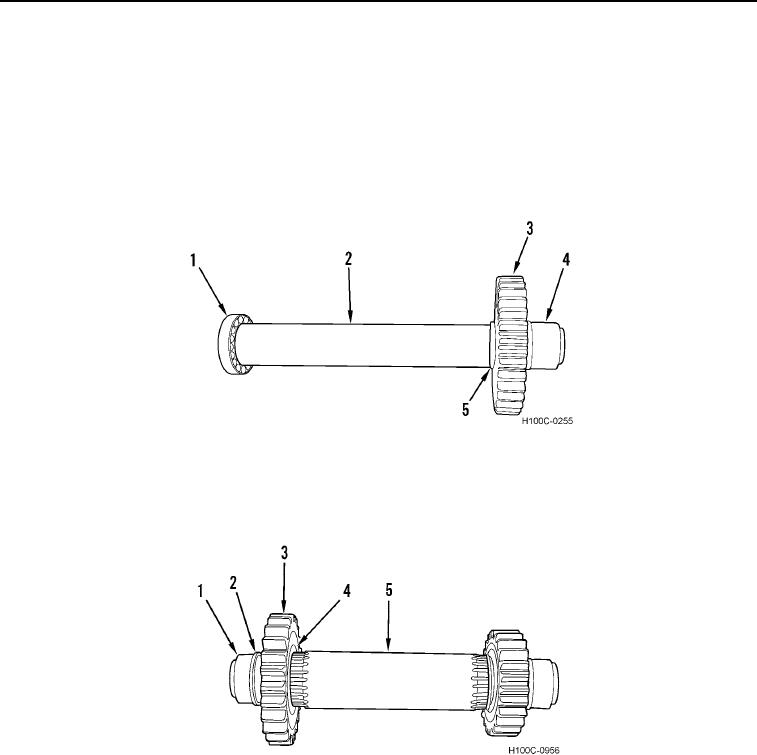
11. Install spacer (Figure 42, Item 4) and main idler gear (Figure 42, Item 3) on idler shaft (Figure 42, Item 2).
12. Install bearing (Figure 42, Item 1) on shaft (Figure 42, Item 2).
13. Install bearing inner race (Figure 42, Item 5) with shoulder toward gear.
Figure 42. Main Idler Gear Installation.
0103
14. Install spacer (Figure 43, Item 4), transmission output high gear (Figure 43, Item 3), spacer (Figure 43, Item 2)
and bearing inner race (Figure 43, Item 1) on gather shaft (Figure 43, Item 5).
Figure 43. Gather Shaft Assembly.
0103
0103-28