
TM 5-3805-255-14
0103
ASSEMBLY CONTINUED
NOTE
Prior to installation in transmission, lubricate all shaft bearing surfaces and bearings with
oil soluble grease.
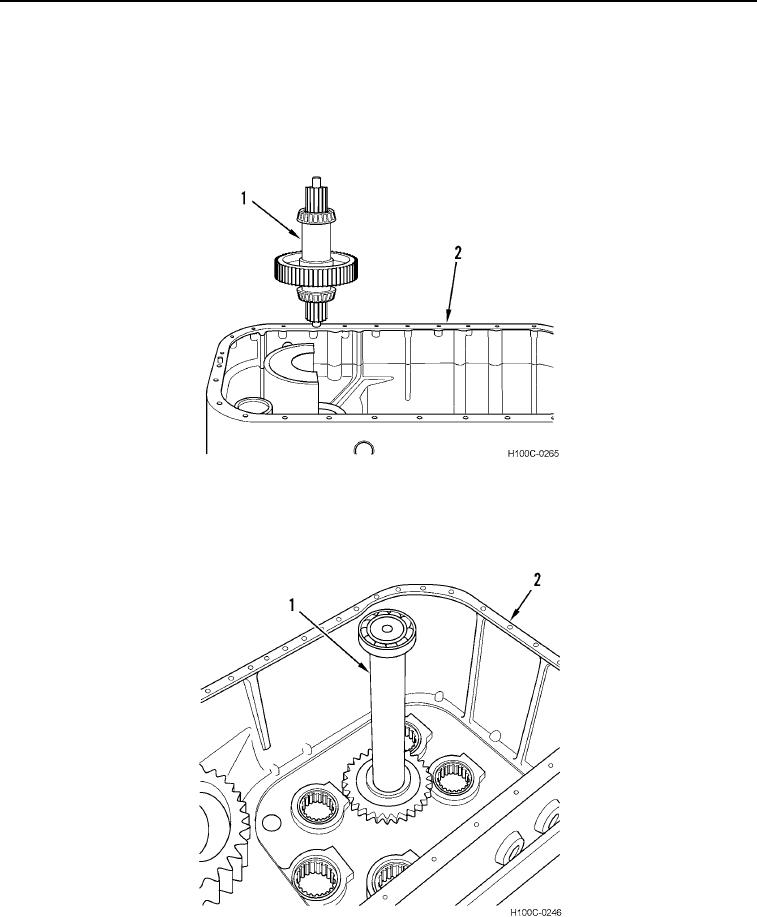
24. Install assembled output shaft (Figure 49, Item 1) in its bore in transmission housing (Figure 49, Item 2).
Figure 49. Output Shaft Installation.
0103
25. Position transmission (Figure 50, Item 2) horizontally. Install main idler shaft and gear assembly (Figure 50,
Item 1) on transmission housing.
Figure 50. Main Idler Shaft and Gear Installation.
0103
0103-32