
TM 5-3805-255-14
0103
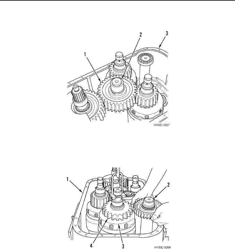
ASSEMBLY CONTINUED
28. Install gear (Figure 53, Item 1) and shaft (Figure 53, Item 2) on transmission housing (Figure 53, Item 3).
Figure 53. Gather Shaft Assembly Installation.
0103
29. Attach lifting tool to directional clutch pack (Figure 54, Item 3) and lower clutch pack into transmission housing
(Figure 54, Item 1) while installing reverse idler shaft assembly (Figure 54, Item 2). Larger gear (Figure 54,
Item 4) on reverse idler shaft is in up position. Remove lifting tool.
Figure 54. Directional Clutch Pack Installation.
0103
0103-34