
TM 5-3805-255-14
0103
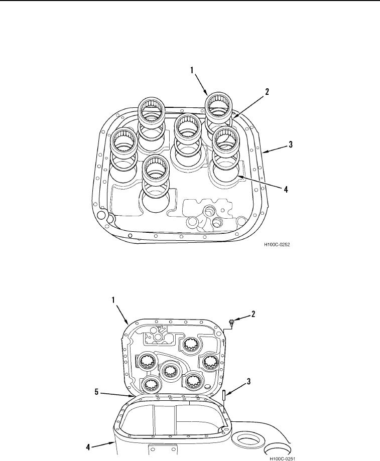
ASSEMBLY CONTINUED
18. Install spacers (Figure 45, Item 2) and bearings (Figure 45, Item 1) in front cover (Figure 45, Item 3).
19. Coat outside diameter of new input shaft seal (Figure 45, Item 4) with sealant. Install seal in front cover (Figure
45, Item 3).
Figure 45. Cover Bearings and Spacers Installation.
0103
20. Install new gasket (Figure 46, Item 5) on transmission housing (Figure 46, Item 4). Install transmission cover
(Figure 46, Item 1) and 20 bolts (Figure 46, Item 2). Be sure cover is positioned on dowels (Figure 46, Item 3).
Figure 46. Front Cover Installation.
0103
0103-30