
TM 5-3805-255-14
0103
ASSEMBLY CONTINUED
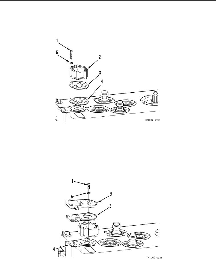
35. Install new gasket (Figure 57, Item 3), range selector valve (Figure 57, Item 2), eight new lockwashers (Figure
57, Item 5), and bolts (Figure 57, Item 1) on valve mounting pad (Figure 57, Item 4). Torque bolts to 19 to
21 lb-ft (26 to 29 Nm).
Figure 57. Range Selector Valve Installation.
0103
NOTE
Be sure directional oil supply cover is in correct alignment.
Do not tighten bolts until directional selector valve has been installed.
36. Install new gasket (Figure 58, Item 3), neutral knockdown valve (Figure 58, Item 2), three washers (Figure 58,
Item 5), and bolts (Figure 58, Item 1) on valve mounting pad (Figure 58, Item 4).
Figure 58. Neutral Knockdown Valve Installation.
0103
0103-38