
TM 5-3805-255-14
0103
ASSEMBLY CONTINUED
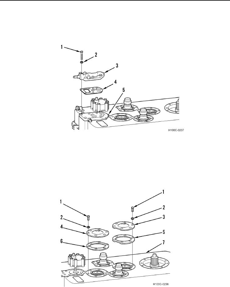
37. Install new gasket (Figure 59, Item 4), directional selector valve (Figure 59, Item 3), six new lockwashers
(Figure 59, Item 2), and bolts (Figure 59, Item 1) on neutral knockdown (Figure 59, Item 5).
38. Torque all bolts (knockdown and selector valve bolts) to 33 to 37 lb-ft (30 to 50 Nm).
Figure 59. Directional Selector Valve Installation.
0103
39. Install new gasket (Figure 60, Item 6), main idler shaft bearing retainer (Figure 60, Item 4), six new
lockwashers (Figure 60, Item 2) and bolts (Figure 60, Item 1) on transmission housing (Figure 60, Item 7).
Torque bolts to 33 to 37 lb-ft (30 to 50 Nm).
40. Install new gasket (Figure 60, Item 5), shaft bearing retainer (Figure 60, Item 3), six new lockwashers (Figure
60, Item 2), and bolts (Figure 60, Item 1) on transmission housing (Figure 60, Item 1). Torque bolts to 33 to
37 lb-ft (30 to 5 Nm).
Figure 60. Shaft Covers Installation.
0103
0103-39