TM 5-3805-255-14
0103
ASSEMBLY CONTINUED
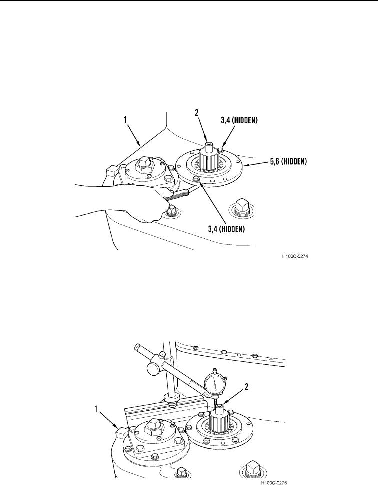
48. Rotate output shaft (Figure 64, Item 2) several times to seat bearings (Figure 64, Item 6).
49. Use a feeler gauge to measure gap between transmission housing (Figure 64, Item 1) and retainer (Figure 64,
Item 5) at each bolt (Figure 64, Item 3). If two readings are not identical, add two readings and divide by two.
50. Add 0.025 in. (0.63 mm) to reading obtained in previous step. Make up a shim pack equal to resulting
thickness. Install shim pack between end cap (Figure 64, Item 4) and transmission housing (Figure 64, Item 1).
51. Install end cap (Figure 64, Item 5), six new lockwashers (Figure 64, Item 4), and six bolts (Figure 64, Item 3).
Torque six bolts in an alternating pattern to final torque of 33 to 37 lb-ft (40 to 50 Nm).
Figure 64. Clearance Measurement.
0103
52. Install a dial indicator on transmission (Figure 65, Item 1) as shown. Position tip of dial indicator on end of
output shaft (Figure 65, Item 2). Place a jack under opposite end of output shaft (do not contact shaft). Use a
pry bar to exert pressure on end of shaft and measure reading on dial indicator. This distance should be within
recommended tolerance of 0.005 to 0.009 in. (0.127 to 0.228 mm). If reading is not within recommended
limitations, shim pack thickness should be corrected. Remove dial indicator.
Figure 65. Output Shaft End-Play Measurement.
0103
0103-42

