TM 5-3805-255-14
0104
DISASSEMBLY CONTINUED
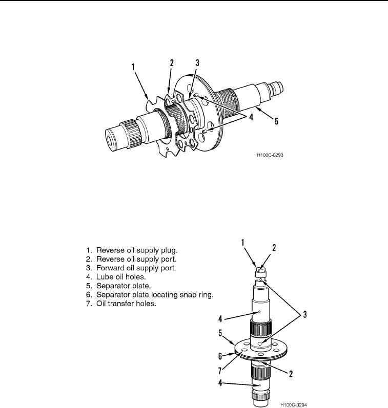
17. Remove disc valve (Figure 17, Item 1), reinforcing disc (Figure 17, Item 2), hook-type seal ring (Figure 17,
Item 3), and two dowel pins (Figure 17, Item 4) from clutch shaft (Figure 17, Item 5). Discard seal ring.
Figure 17. Clutch Shaft Disassembly.
0104
NOTE
Shaft is serviced as an assembly only. If snap rings, shaft, or separator plate are
damaged, entire assembly must be replaced.
Figure 18. Clutch Shaft Identification.
0104
END OF TASK
0104-10

