TM 5-3805-255-14
0104
ASSEMBLY CONTINUED
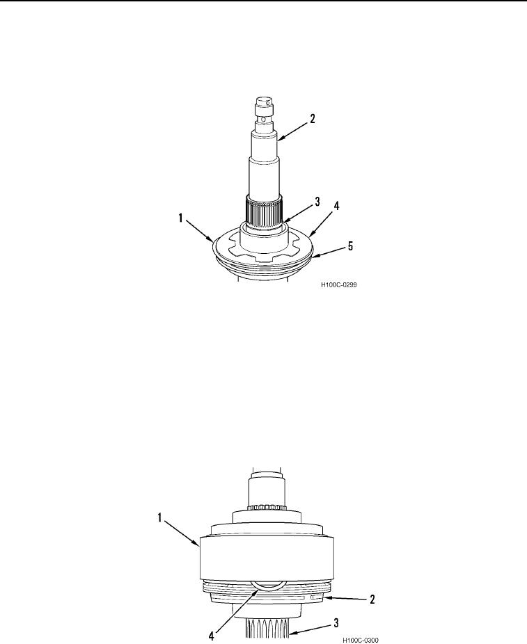
11. Invert shaft (Figure 25, Item 2). Install new hook-type seal ring (Figure 25, Item 3) in groove on shaft.
12. Install new O-ring (Figure 25, Item 1) on outer diameter of separator plate (Figure 25, Item 4). Coat seals with
grease. Coat rectangular seal (Figure 25, Item 5) on clutch piston (Figure 25, Item 4) with grease.
Figure 25. Seal Lubrication.
0104
13. Install special snap ring groove filler tool (Figure 26, Item 2), bevel edge up, in groove of piston housing
(Figure 26, Item 1). Lubricate groove area and mouth of piston housing with heavy grease.
14. Install piston housing (Figure 26, Item 1) on shaft assembly (Figure 26, Item 3).
NOTE
O-ring is larger in diameter than separator plate. This design allows inside diameter of
piston housing to compress O-ring to proper fit.
15. Install new O-ring seal (Figure 26, Item 4) into housing while applying pressure to piston housing (Figure 26,
Item 1). Push piston housing over O-ring seal and groove filler tool (Figure 26, Item 2).
Figure 26. Piston and O-Ring Installation.
0104
0104-14

