
TM 5-3805-255-14
0104
CLEANING AND INSPECTION
000104
1. Clean and inspect all parts of clutch assembly IAW General Maintenance Instructions (WP 0019).
2. Inspect splines on all shafts and drive gears for excessive wear or damage. Replace as necessary.
3. Inspect sintered bronze and steel discs for wear, signs of burning, and/or warping. Replace as necessary.
END OF TASK
ASSEMBLY
000104
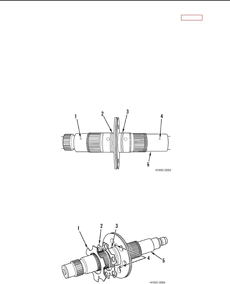
1. Place shaft (Figure 19, Item 5) horizontally on bench. Install new hook-type seal rings (Figure 19, Items 2
and 3) on grooves of inner shaft.
NOTE
Perform step 2 only if assembling directional clutch.
2. Be sure roll pins (Figure 19, Items 1 and 4) are in place and bores are clean.
Figure 19. Clutch Shaft Assembly.
0104
3. Install two dowel pins (Figure 20, Item 4) in separator plate (Figure 20, Item 3). Install a reinforcing disc
(Figure 20, Item 2) on each side of separator plate.
4. Install a disc valve (Figure 20, Item 1) on each side of separator plate (Figure 20, Item 3). Align reinforcing
discs (Figure 20, Item 2) and disc valves with two dowel pins (Figure 20, Item 4).
Figure 20. Reinforcing Discs and Disc Valves Installation.
0104
0104-11