
TM 5-3805-255-14
0106
ASSEMBLY
000106
Charging Pump
000106
CAUTION
Lubricate bushings and gears with hydraulic fluid. Rotate pump driveshaft to be sure
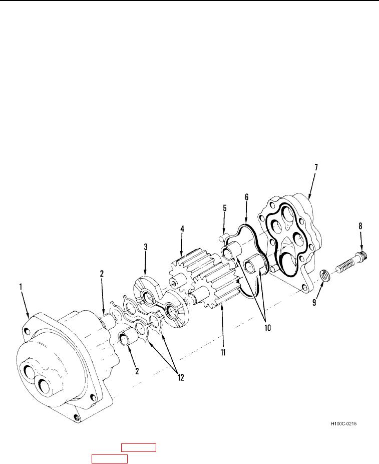
1. Install two bushings (Figure 2, Item 10) into pump cover (Figure 2, Item 7).
2. Install two bushings (Figure 2, Item 2) into pump body (Figure 2, Item 1).
3. Install two new seals (Figure 2, Item 12) on wear plate (Figure 2, Item 3).
4. Install wear plate (Figure 2, Item 3), driven gear (Figure 2, Item 4), drive gear (Figure 2, Item 11), and two
dowel pins (Figure 2, Item 5) in pump body (Figure 2, Item 1).
5. Install new seal (Figure 2, Item 6) on pump cover (Figure 2, Item 7).
6. Install pump cover (Figure 2, Item 7), six new lockwashers (Figure 2, Item 9), and bolts (Figure 2, Item 8) on
pump body (Figure 2, Item 1). Torque bolts to 28 to 32 lb-ft (37.96 to 43.38 Nm).
Figure 2. Transmission Oil Pump (Late Type).
0106
7. Install pump in torque converter (WP 0102).
8. Install torque converter (WP 0047).
END OF TASK
END OF WORK PACKAGE
0106-3/(4 blank)