
TM 5-3805-255-14
0111
ASSEMBLY CONTINUED
000111
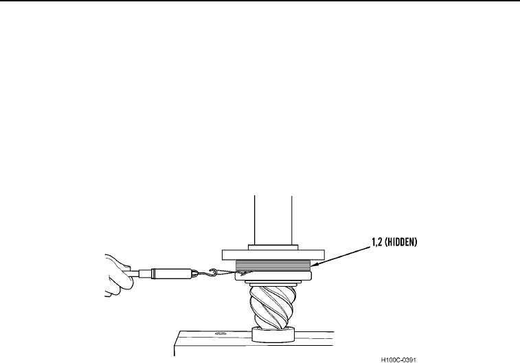
9. Wrap a soft iron wire around outer circumference of bearing cage assembly (Figure 21, Item 1). Pull on a line
tangent to outside diameter of cage with a pound scale hooked to wire as shown. With flange (Figure 21, Item
2) held stationary, rotate cage with pull of spring scale.
NOTE
Use rotating torque, not starting torque.
10. Read torque required to keep cage moving (starting torque will be higher). Scale should read between 2 and 6
lb (0.746 to 2.240 kg).
11. If torque is not within recommended limitations, install a thinner spacer as installed in step 6 to decrease
preload.
Figure 21. Rotating Torque Measurement.
0111
0111-16