TM 5-3805-255-14
0111
ASSEMBLY CONTINUED
000111
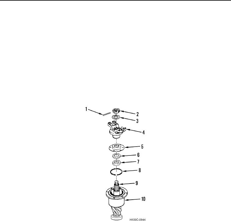
12. Remove pinion nut (Figure 22, Item 2), washer (Figure 22, Item 3), and companion flange assembly (Figure
22, Item 4) from pinion bearing cage (Figure 22, Item 10).
13. Install seal (Figure 22, Item 8) in groove of bearing cage (Figure 26, Item 10) with split at top side of assembly.
14. Coat new oil seal (Figure 22, Item 7), new felt seal (Figure 22, Item 6), and oil seal retainer (Figure 22, Item 5)
with lubricant. Install oil seal in oil seal retainer. Be sure lip of seal is toward bearing cage (Figure 22, Item 10).
15. Position assembled oil sealed retainer (Figure 22, Item 5) on bearing cage (Figure 22, Item 10). Reinstall
companion flange (Figure 22, Item 4), washer (Figure 22, Item 3), and pinion nut (Figure 22, Item 2) on pinion
shaft (Figure 22, Item 9). Tighten pinion nut to 500 to 700 lb-ft (678 to 949 Nm).
NOTE
Do not back off pinion nut to align cotter pin holes
16. Align cotter pin holes in pinion shaft (Figure 22, Item 9) with pinion nut (Figure 22, Item 2). Install new cotter pin
(Figure 22, Item 1).
Figure 22. Companion Flange Installation.
0111
0111-17

