
TM 5-3805-255-14
0111
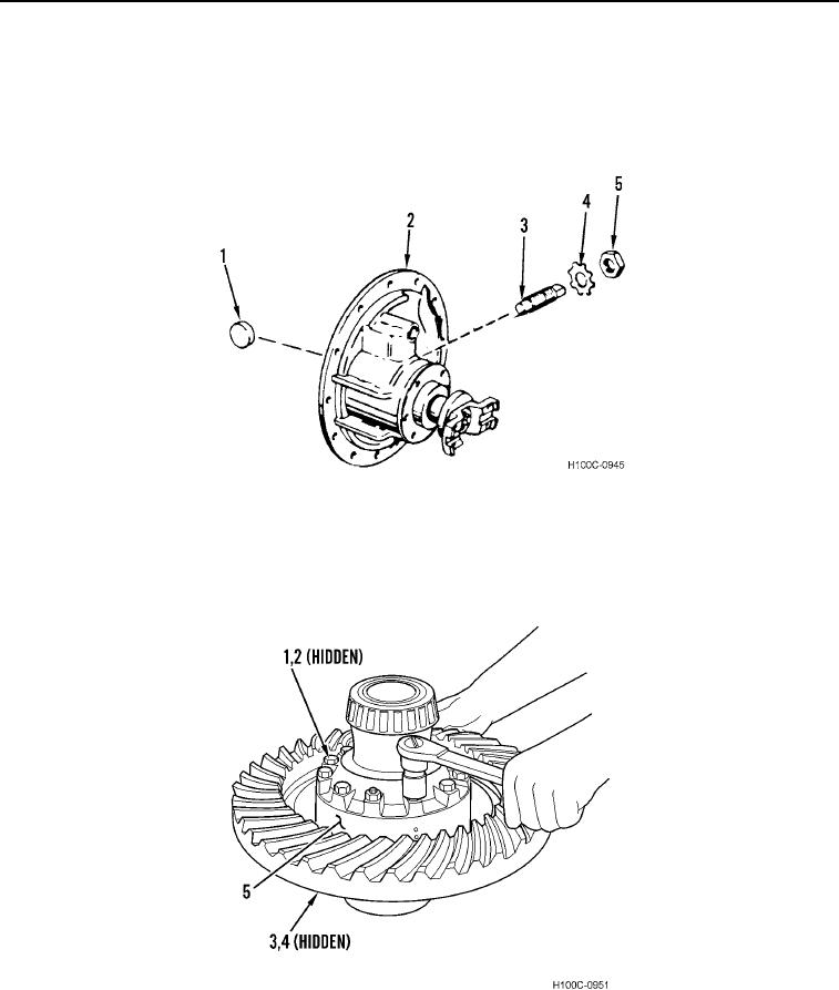
ASSEMBLY CONTINUED
000111
20. Install new lockwasher (Figure 24, Item 4) and nut (Figure 24, Item 5) on adjusting screw (Figure 24, Item 3).
21. Install adjusting screw (Figure 24, Item 3) in carrier housing (Figure 24, Item 2) far enough that thrust block
(Figure 24, Item 1) can be installed from inside differential carrier. Lubricate thrust block with lubricant and
install it on end of adjusting screw.
Figure 24. Adjusting Screw Installation.
0111
22. Install plain half (Figure 25, Item 3) on flanged half (Figure 25, Item 5). Install 12 bolts (Figure 25, Item 1), flat
washers (Figure 25, Item 2), and hex nuts (Figure 25, Item 4). Tighten bolts to a preliminary torque of 40 lb-ft
(54 Nm). Tighten bolts to a final torque of 200 lb-ft (271 Nm).
Figure 25. Ring Gear Installation.
0111
0111-19