
TM 5-3805-255-14
0111
ASSEMBLY CONTINUED
000111
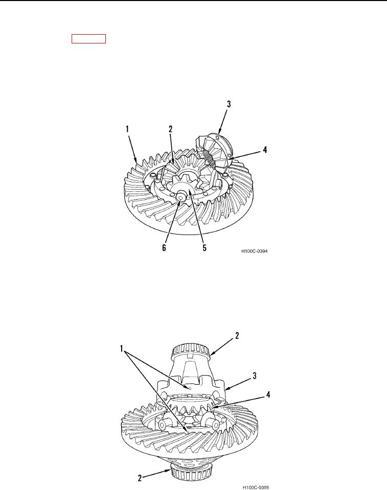
25. Lubricate spider (Figure 27, Item 6), four spider gears (Figure 27, Item 2), and thrust washers (Figure 27, Item
5) with lubricant (WP 0018).
26. Place spider (Figure 27, Item 6), spider gears (Figure 27, Item 2), and thrust washers (Figure 27, Item 5) in
position in case half (Figure 27, Item 1).
27. Install remaining side gear (Figure 27, Item 4) and thrust washer (Figure 27, Item 3) on case half (Figure 27,
Item 1).
Figure 27. Spider Installation.
0111
28. Align mating marks on case halves (Figure 28, Item 1) and secure assembly (Figure 28, Item 3) with four
equally spaced capscrews and hex nuts.
29. Check assembly for free rotation of differential gears (Figure 28, Item 4). Correct if necessary.
30. If ring gear thrust bearings (Figure 28, Item 2) were removed, press new bearings squarely to each case half
(Figure 28, Item 1). Use a suitable sleeve and press only on bearing inner race.
Figure 28. Bearing Installation.
0111
0111-21