
TM 5-3805-255-14
0111
ASSEMBLY CONTINUED
000111
31. Install remaining eight bolts (Figure 29, Item 3) and hex nuts (Figure 29, Item 4). Tighten all 12 bolts and hex
nuts to 190 to 200 lb-ft (257 to 271 Nm).
32. Install lockwire on bolts (Figure 29, Item 3).
33. Lubricate two bearings (Figure 29, Item 2) with lubricant (WP 0018).
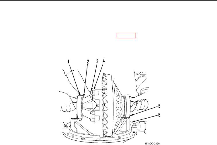
34. Place two bearing cups (Figure 29, Item 1) over differential bearing cones (Figure 29, Item 2) and position
differential assembly (Figure 29, Item 5) in carrier (Figure 29, Item 6).
Figure 29. Differential Installation.
0111
0111-22