
TM 5-3805-255-14
0121
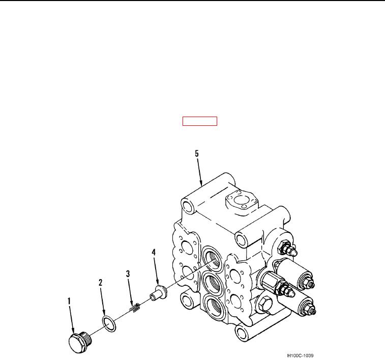
ASSEMBLY CONTINUED
7. Assemble and install three check valves as follows:
a. Install three new O-rings (Figure 20, Item 2) on valve plugs (Figure 20, Item 1) being careful not to damage
O-rings on plug threads.
b. Install three poppets (Figure 20, Item 4) in housing bores (Figure 20, Item 5).
c.
Install three valve springs (Figure 20, Item 3) in poppet recesses.
NOTE
Be sure valve springs center in plug recesses as plugs are installed to housing bores.
d. Lubricate three O-rings on plugs with clean oil (WP 0131) and install plugs to housing bores. Tighten plugs
securely.
Figure 20. Main Control Valve (Plunger Cap End).
0121
0121-20