TM 5-3805-255-14
0121
ASSEMBLY CONTINUED
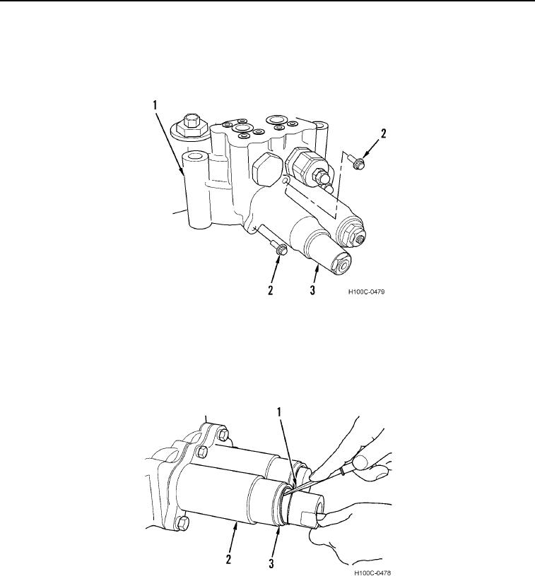
16. Place plunger cap (Figure 25, Item 3) over detent assembly and firmly against seal plate with screw holes in
cap, plate, and valve housing (Figure 25, Item 2) properly aligned. Install two screws (Figure 25, Item 1) to
valve body. Tighten screws securely.
Figure 25. Plunger Cap Installation.
0121
17. Inspect spacer (Figure 26, Item 3) and snap ring (Figure 26, Item 1) for damage.
18. Install spacer (Figure 26, Item 3) and snap ring (Figure 26, Item 1) on detent sleeve (Figure 26, Item 2) on
being sure snap ring is properly seated in detent sleeve groove.
Figure 26. Spacer and Snap Ring Installation.
0121
0121-24

