• Home
  • Download PDF
  • Order CD-ROM
  • Order in Print
Figure 20. Main Control Valve (Plunger Cap End).
Figure 22. O-Ring and Backup Ring Installation.

Maintenance Manual For Loader, Scoop Type, Ded 4 X 4, Articulated Frame Steer, 4.5 To 5 Cu. Yd.
Page Navigation
  1248    1249    1250    1251    1252  1253  1254    1255    1256    1257    1258  
img
.
TM 5-3805-255-14
0121
ASSEMBLY CONTINUED
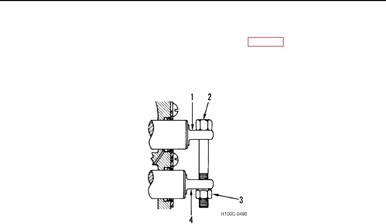
8. Assemble and install valve plungers as follows:
a. Lubricate valve plungers (Figure 21, Items 1 and 4) with clean oil (WP 0018) and install in respective
bores.
b. Align eyes in ends of plungers (Figure 21, Items 1 and 4) and install a 1/2 in. x 4NF capscrew (Figure 21,
Items 2) and hex nut (Figure 21, Items 3). Tighten nut hand tight.
Figure 21. Plunger Bolt and Nut Installation.
0121
0121-21


Privacy Statement
Press Release
Contact

© Copyright Integrated Publishing, Inc.. All Rights Reserved.