
TM 5-3805-255-14
0121
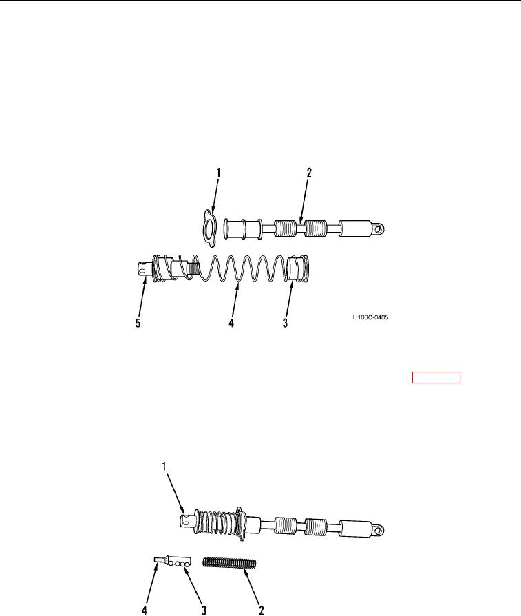
ASSEMBLY CONTINUED
11. Install spring seat (Figure 23, Item 1) on plunger (Figure 23, Item 2) against seal plate (Figure 23, Item 3).
CAUTION
Use caution to prevent damage to detent ball holes in plunger pin. Failure to follow this
caution may result in damage to equipment.
12. Insert plunger pin (Figure 23, Item 2) through remaining spring seat (Figure 23, Item 5) and in plunger spring
(Figure 23, Item 4). With rod used during disassembly, screw plunger pin assembly in plunger and tighten
securely.
Figure 23. Plunger Assembly.
0121
13. Lubricate detent cam assembly (Figure 24, Item 4) liberally with multi-purpose grease (WP 0018).
14. Install detent cam (Figure 24, Item 4) and spring (Figure 24, Item 2) in bore of plunger pin (Figure 24, Item1).
15. Place punch within bore of detent sleeve; depress detent cam with punch, place detent balls (Figure 24, Item
3) in respective holes and slide sleeve over detent cam assembly. Release punch.
Figure 24. Plunger Assembly.
0121
0121-23