Engine Tune-Up
HYDRAULIC GOVERNOR (EG-B ELECTRIC) AND INJECTOR RACK CONTROL
ADJUSTMENT
6, 8 and 12V ENGINES
assembly is required when the control box receives
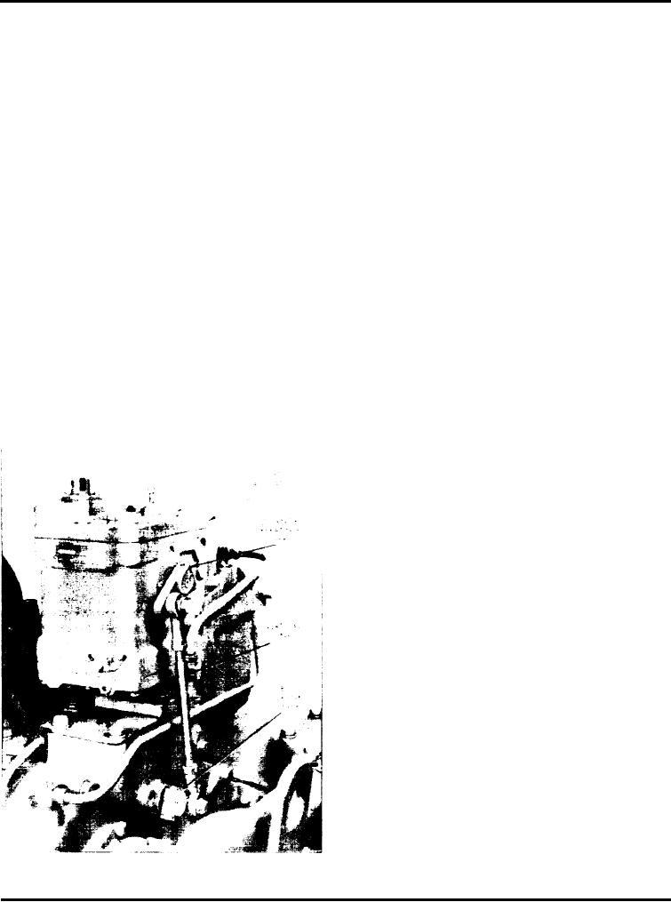
The Woodward EG-B2C series governor (Fig. 1) is of
load signals from an engine driven alternator.
the electric type. It can be operated as an isochronous
(zero speed droop) governor or as a speed' droop
governor. As an isochronous governor installed on an
The output signal of the control box serves as the
engine operating alone, it will maintain a constant
input signal to the hydraulic actuator; the actuator in
turn controls the fuel to the engine.
speed for all loads within the capacity of the engine,
except momentarily at the time a load change occurs.
Paralleled with other EG-governors, it will render
The EC-B hydraulic actuator has a centrifugal head
proportional load division with isochronous control.
assembly to control the engine during starting; also, it
Paralleled with dissimilar governors or with an infinite
will limit the maximum engine speed if the control
bus (i.e., commercial power), the EC-B2C governor
box signal is interrupted or if it fails in such a manner
c a n be operated as a conventional speed droop
as to call for maximum fuel.
governor, and the load carried by the engine will be a
function of the governor speed setting and speed
Used with the control box, the EG-B actuator
droop setting.
provides, in effect, two governors in one: an electric
governor and a centrifugal governor, each indepen-
dently capable of positioning the terminal (output)
The governor consists essentially of three separate
shaft. During normal operation, the electric governor
assemblies: a control box, a speed adjusting potenti-
controls fuel to the engine. The actuator is adjusted so
ometer, and a hydraulic actuator. A resistor box
that, if the electric control signal is interrupted, the
electric section moves the fuel. linkage to maximum
fuel. When the speed reaches the level for which the
centrifugal governor is set (always a level higher than
that for which the electric governor is set), this section
assumes and maintains control of the engine. Speed
can then be reduced, if desired, by lowering the speed
setting on the centrifugal governor. Should the control
box fail in such a way as to emit a continuous signal
calling for a decrease in fuel, the unit would shut
down.
The essential element of the electric section of the
actuator is an electro-hydraulic transducer which
directs pressure oil to and from the power piston
which actuates the fuel mechanism. The transducer
consists of a polarized magnet to which is attached the
pilot valve plunger controlling oil flow to and from the
power piston. The solenoid responds to the push-pull
output of the electric control box and, in so doing,
moves the pilot valve plunger up or down. Through
c o n n e c t i n g linkage, the power piston moves the
terminal (output) shaft of the actuator. The engine
fuel linkage attaches to the actuator terminal shaft.
The governor (actuator) uses oil from the engine
lubrication system.
For more detailed information on the electrical section
and on servicing the EC-B2C governor, refer to the
Woodward Governor Company's Bulletins 37709 and
Fig. 1 - Governor Mounted on Engine
37706 (also 37702 for type EG-B1 governor).
Page 140

