Engine Tune-Up
9. Remove the clevis pin from the fuel rod and the
right cylinder bank injector control tube lever.
10. Install the clevis pin in the fuel rod and the left
cylinder bank injector c o n t r o l tube lever. Then
position the No. 1L injector rack control lever as
outlined in Steps 7 and 8.
11. Install the clevis pin in the fuel rod and the right
cylinder bank injector control tube lever. Recheck the
No. 1R and 1L injector rack control levers as in
Step 8. Check for and eliminate any deflection in the
fuel rods. If the settings are correct, both injector racks
will be in the full-fuel position and snug on the ball
end of the control levers.
12. Manually hold the No. 1R injector rack in the
full-fuel position by means of the injector control tube
lever. Turn down the inner adjusting screw of the
No. 2R injector rack control lever until the injector
rack moves into the full-fuel position. Turn the outer
adjusting screw down until it bottoms lightly on the
injector control tube. Then alternately tighten both the
inner and outer adjusting screws.
NOTE: Overtightening of the injector, rack
control lever adjusting screws during installa-
tion or adjustment can result in damage to the
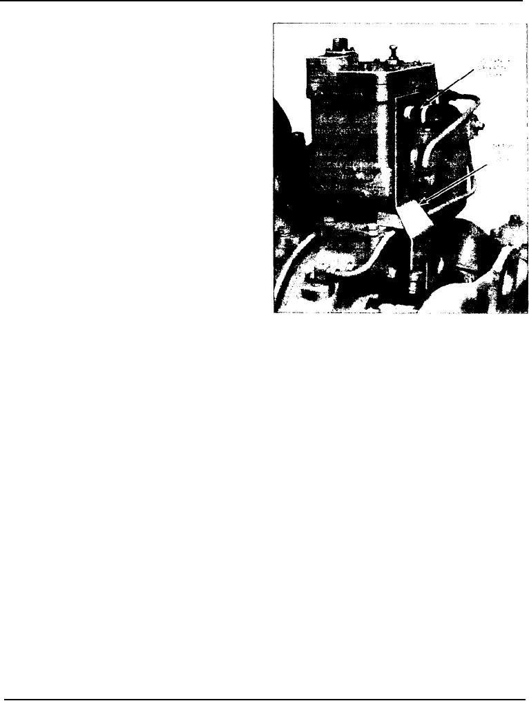
Fig. 4 - Governor Operating Lever in Position
injector control tube. The recommended torque
of the adjusting screws is 24-36 in-lbs (3-4
Nm).
vertical link are in alignment.
13. Recheck the No. 1R injector rack to be sure it has
18. Install and tighten the vertical link attaching bolts.
remained snug on the ball end of the rack control
lever while positioning the No. 2R injector rack. If the
19. As an additional check, the governor operating
rack of No. 1R injector has become loose, back off the
lever should be in a position indicating maximum on
inner adjusting screw on the No. 2R injector rack
the dial indicator (Fig. 6) when the injector rack
control lever slightly and tighten the outer adjusting
control levers are in the full-fuel position. If not,
screw. When the settings are correct, both injector
readjust the vertical link.
racks will respond in the same manner on the ball end
of their respective rack control levers.
20. Use a new gasket and install the valve rocker cover
on each cylinder head.
14. Position the remaining injector rack control levers
on the right and left bank cylinder heads as outlined
in Step 12. When the settings are correct, all of the
Governor Adjustments
injector racks will be snug on the ball end of the
control levers when the injector control, tube levers are
The centrifugal governor section of the actuator has
held in the full-fuel position.
three operating adjustments.
15. Turn the terminal shaft clockwise to the no-fuel
1. Speed setting: An external adjustment used to set the
position. Then place the governor operating lever on
speed at which the centrifugal governor will control.
the terminal shaft so that the bolt hole in the lever is
aligned with the center of the slot in the linkage gage
2. Speed droop: An internal adjustment used to permit
(Fig. 4). Remove the gage and tighten the clamping
parallel operation of units controlled by the centrifu-
bolt on the lever.
gal governor.
16. Move the bell crank lever to the no-fuel position.
3. Needle Valve: An external adjustment used to
stabilize the centrifugal governor.
17. Adjust the length of the vertical link so the bolt
Page 142

