Engine Tune-Up
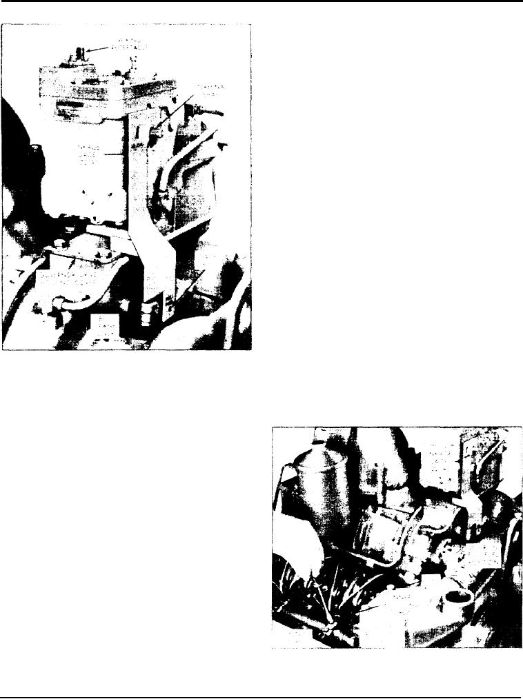
3. Remove the vertical link assembly (Fig. 1) from the
governor operating lever and the bell crank lever.
4. Loosen the clamping bolt and slide the governor
operating lever from the governor terminal shaft.
5. Place the linkage gage J 22195 over the governor
terminal shaft and insert the gage pin in the bell crank
lever bolt hole (Fig. 2). The tang on the side of the
gage should just touch the top of the governor drive
housing when the gage is properly positioned. The
gage will hold the injector control racks in the full-
fuel position while the levers are being adjusted.
6. Remove the clevis pin from the fuel rod and the left
cylinder bank injector control tube lever.
7. Turn the inner adjusting screw of the No. IR
injector rack control lever down (Fig. 3) until a slight
movement of the control tube is observed, or a step-up
in effort to turn the screw driver is noted. This will
p l a c e the No. 1R injector rack in the full-fuel
position. Turn the outer adjusting screw down until it
bottoms lightly on the injector tube. Then alternately
tighten both the inner and outer adjusting screws.
CAUTION: Avoid setting the rack too tight,
causing the fuel rod to bend.
8. To be sure the control lever is properly adjusted,
Fig. 2 - Linkage Gage in Position
press down on the injector rack with a screw driver or
finger tip. The setting is sufficiently tight if the rack
Position Injector Rack Control Levers and
returns to its original position when the pressure is
Adjust Governor Linkage
released.
After adjusting the exhaust valves and timing the fuel
injectors. position the injector rack control levers and
adjust the governor linkage.
The position of the injector control racks must be
correctly set in relation to the governor. Their position
determines the amount of fuel injected into each
cylinder and ensures equal distribution of the load.
The letters R and L indicate the injector location in
the right or left cylinder bank, viewed from the rear of
the engine. Cylinders are numbered starting at the
front of the engine on each cylinder bank. Adjust the
No. IR injector rack control lever first to establish a
guide for adjusting the remaining levers.
1. Clean and remove the valve rocker covers.
2. Loosen all of the inner and outer injector rack
control lever adjusting screws on both injector control
Fig. 3 - Positioning No. 1R Injector Rack
tubes. Be sure all of the injector rack control levers are
Control Lever
free on the control tubes.
Page 141

