
7. Remove lower spring and side gear from differential
10. If necessary to remove center cam from spider, use
case (Fig. 74).
three small screwdrivers or tapered wedges to spread
snap ring into spider (Fig. 77). Press center cam out
through spider.
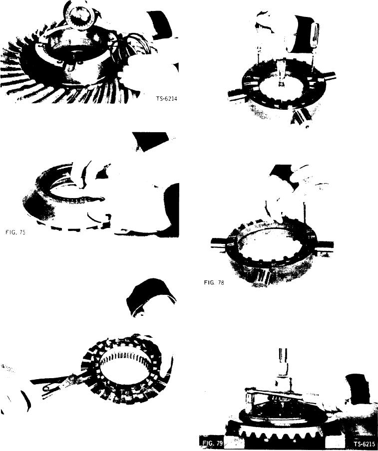
8. Lift spring retainer from driven clutch (Fig. 75).
FIG. 77
TS-6112
11. Remove snap ring from spider (Fig. 78).
9. Remove holdout ring, using expanding snap ring pliers
(Fig. 76).
TS-6113
Disassembly of Differential Case Parts
1. Remove nuts that secure ring gear to case half. Place
case half and ring gear in press and apply light pres-
sure to hold parts while removing nuts (Fig. 79).
FIG. 76
TS-7683
[28]