5. Press bearing cups into pinion bearing cage (Fig. 94).
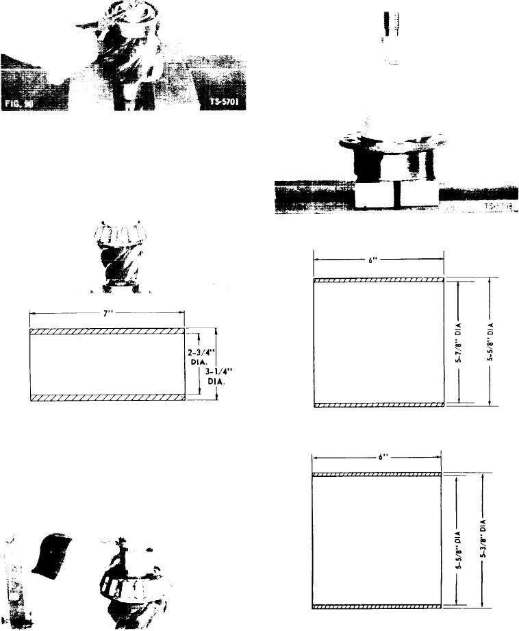
2. Install inner pinion bearing retaining ring (Fig. 90).
Bearing driver dimensions are shown in Figs. 95 and
96.
3. Press center pinion bearing cone onto pinion shaft (Fig.
91). Bearing driver dimensions are given in Fig. 92.
1/32" DIA RADIUS ALL CORNERS
1/32" DIA RADIUS ALL CORNERS
TS-6221
FIG. 92
TS-6284
FIG. 95
4. A pinion bearing spacer and shim kit is provided for
service repair of differential and carrier assemblies.
This kit, consisting of a spacer and quantity of shims,
is used to obtain proper pinion bearing preload as
described below. Position bearing spacer and one
,010" shim on pinion shaft (Fig. 93).
1/3" DIA RADIUS ALL CORNERS
TS-6222
FIG. 96
[33]

