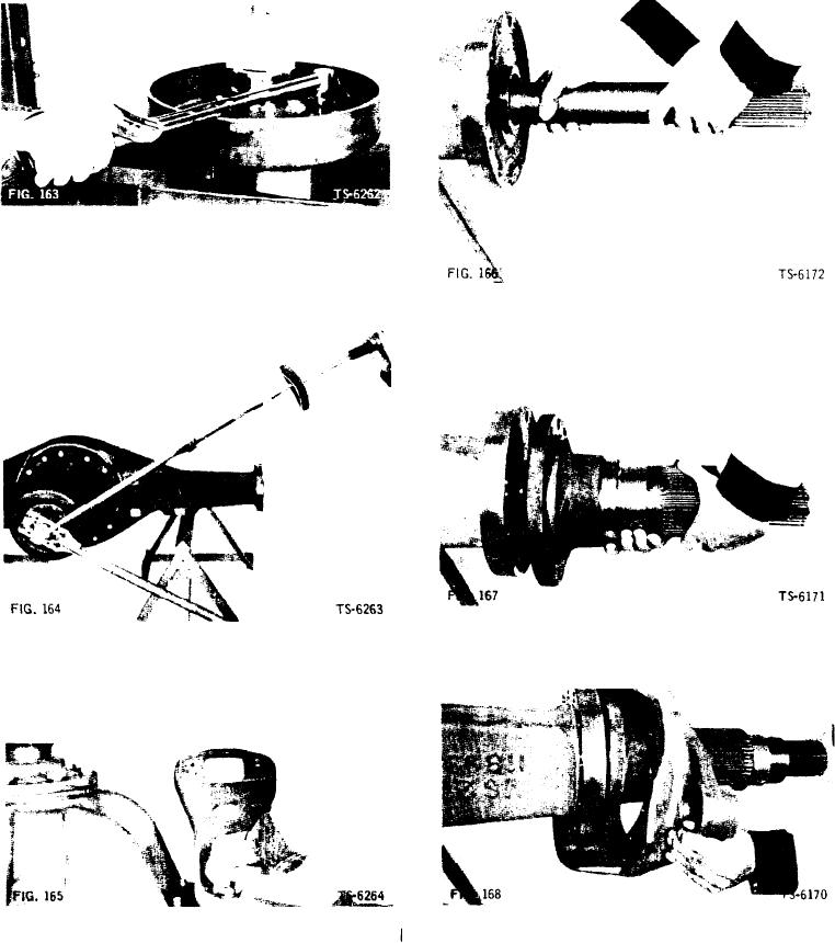
11. Slide axle shaft into position in axle housing so that
8. Position parking brake drum on companion flange,
splines engage differential side gear. Position shaft
taking care to match punch marks made at disassem-
so that end having retaining ring groove for sun
bly. Secure parts with bolts, nuts, and lockwashers.
gear is toward the outside (Fig. 166).
Tighten bolts to specified torque (Fig. 163). When torqu-
ing bolts, place companion flange under light pres-
sure in press to hold assembled parts. Do not score or
distort parking brake drum by clamping in o vise.
9. Position assembled parking brake drum and compan-
ion flange on pinion shaft. Secure with flat washer and
companion flange nut. Torque nut to 600 ft. lbs. (Fig.
1641. Install cotter pin to retain nut.
12. Position spindle on spindle support assembly (Fig.
167).
13. Position brake spider on spindle (Fig. 168).
10. Position air chamber brackets and spacers on axle
housing; secure each bracket with two bolts and lock-
washers. Tighten finger tight only to permit alignment
of bracket after broke camshaft is installed (Fig. 165).
[48]

