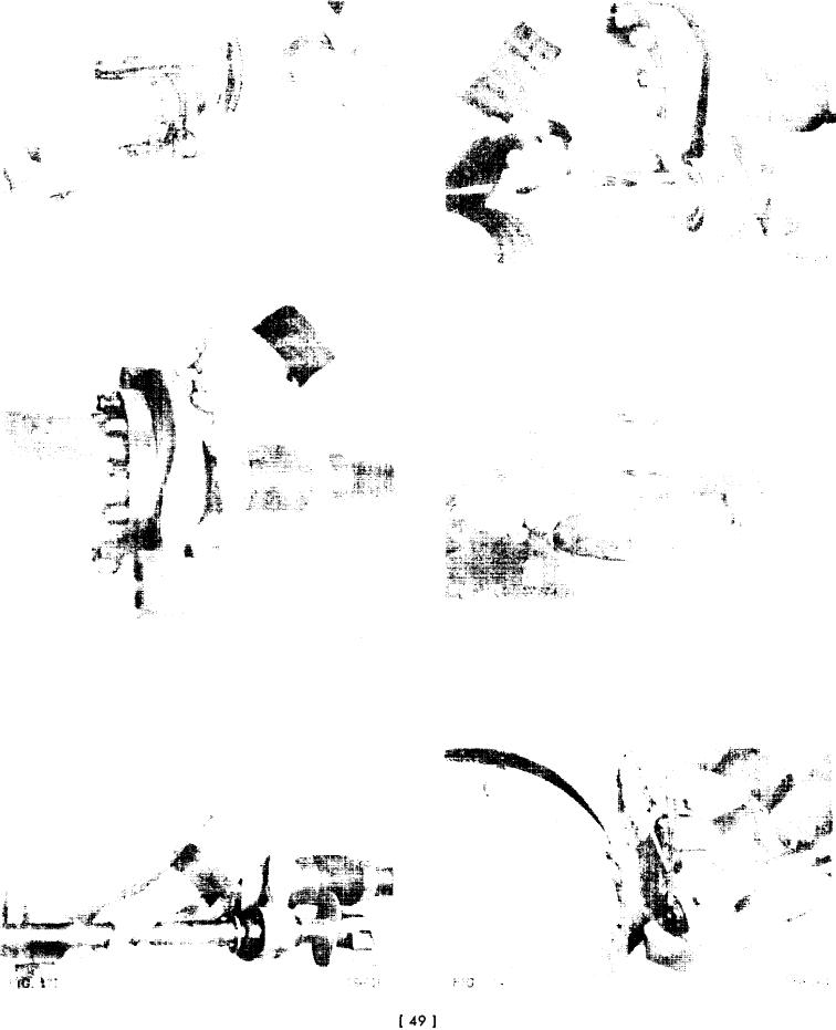
14. Secure spindle and brake spider to axle housing with
17. Seat felt grease retainer in recess in brake spider.
bolts, lockwashers, and nuts and tighten to specified
Install retaining ring in retaining ring groove. (Fig.
torque (Fig. 169).
172).
15. Tap brake camshaft bushing into brake spider (Fig.
170).
18. Position air chamber bracket and spacers, which were
previously installed, so that there is no binding be-
tween cam shaft and air chamber bracket bushing.
Tighten bracket mounting bolts to specified torque
(Fig. 173).
19. Position slack adjuster on cam shaft. Secure with re-
taining ring and washer (Fig. 174). Be sure to in-
stall slack adjuster so that adjusting screw points in
16. Position thrust washer and "O" ring on brake cam
same direction as before disassembly. In some appli-
shaft. Insert cam shaft through bushing in brake
cations adjusting screw is adjacent to air chamber
spider and position felt grease retainer, grease
bracket. In others it is as shown in Fig. 174.
washer, and retaining ring on cam shaft (Fig. 171).

