
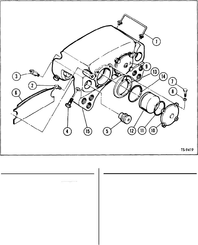
Fig. 1. Brake Head Assembly -Exploded View
Quantity
Ref.
Ref.
Quantity
DESCRIPTION
Per Assy.
No.
DESCRIPTION
Per Assy.
No.
8
W a s h e r , Flat (Hardened) - - - - - - - - - - - - - - - - - - - -
8.
Tube and Nut, Assembly of
1
1.
1
9.
Cop, Piston Retaining - Inlet - - - - - - - - - - - - - -
1
Valve, Hydraulic Bleeder
2.
--------------------
1
Cap, Piston Retaining -
10.
1
Valve, Hydraulic Bleeder- - - - - - - - - - - - - - - - - - - -
3.
---------------------
2
4.
11.
Bolt, Hex Head, Self Locking,
Packing, Preformed
---------------------------
4
B u t t o n Type - - - - - - - - - - - - - - - - - - - - - - - - - - - - - - - - - - - - - - -
4
Piston
12.
--------------------------------
4
Pin, Retaining
5.
------------------------------------
4
Boot
13.
---------------------------------
Carrier and Lining, Assembly of - - - - - - - - - - - - - - -
2
6.
4
Packing,
Preformed
14.
--------------------
7.
Bolt, Hex Head, 0.375-16
1
8
Torque Plate, Assembly of
U N C - 2 A Thread (Grade 5) -
15.
---------------
---------------
[1]