MAINTENANCE
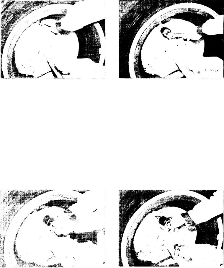
Fig. 3. Loosen Locking Bolts
Fig. 5. loosen Unlocked Pin
Inspect brake assembly daily to insure that all bolts are
3. Place pipe coupling over end of unlocked pin. Cover
tight and there ore no leaks. Inspect for boot deterioration
open end of coupling with the two large flat washers.
and lining wear. Linings should be replaced when friction
Insert bolt in drilled and tapped hole on end of unlocked
material is worn to 1/8" thickness. linings can be removed
pin and turn in a clockwise direction with a wrench to
and replaced without removing rims.
loosen unlocked pin as shown in Figure 5.
4. When pin turns freely, remove extracting device and
Replace excessively worn brake linings as follows:
remove pin as shown in Figure 6.
1. Refer to Figure 3 and loosen the two locking bolts at the
5. Using a large punch and a hammer drive the second
most accessible end of the brake head.
unlocked pin away from disc as shown in Figure 7. Ac-
cess to second unlocked pin can best be gained by
2. Remove the unlocked pin from the side of brake head
working through hole vacated by first unlocked pin
closest to the differential. A device consisting of a 2"
guiding punch next to edge of disc.
diameter pipe coupling, two large flat washers and a
bolt the same diameter and thread size as the hole
6. After driving back second unlocked pin, brake linings
drilled and tapped in the retaining pin, as shown in
can be removed by rotating along outer diameter of
Figure 4, may be helpful in extracting the unlocked pin.
disc and out of brake head assembly.
Fig. 6. Remove Unlocked Pin
fig. 4. Pin Removal Device
[3]

