
OVERHAUL INSTRUCTIONS
The following instructions will cover the disassembly and
tire assembly has been removed and the brake assembly is
reassembly of the caliper type disc brake assembly in a se-
to be completely overhauled.
quence that will normally be followed after the wheel and
DISASSEMBLY
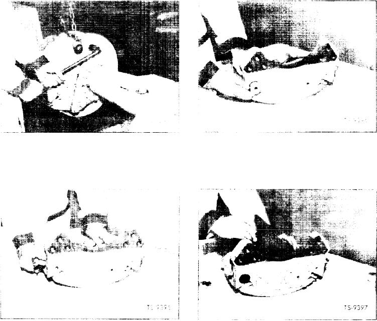
3. Loosen two of the four locking bolts with wrench as
1. With machine securely blocked and wheel and tire as-
shown in Figure 12.
sembly removed, attach a chain hoist to brake head
assembly with bolts and flatwashers through drilled and
4. Remove the two unlocked pins by pressing outward as
tapped holes in retaining pins as illustrated in Figure
illustrated in Figure 13.
11, then remove mounting bolts.
Fig. 11. Attach Hoist and Remove Mounting Bolts
Fig. 13. Remove Unlocked Pins
2. With the aid of hoist, place brake head assembly on
5. With two unlocked pins removed, both carrier and lin-
work bench or other working surface to be used for dis-
ing assemblies may be easily removed by simply lifting
assembly of brake head.
outward as shown in Figure 14.
Fig. 12. Loosen locking Bolts
Fig. 14. Remove Carrier and lining Assemblies
[5]