DESCRIPTION AND OPERATION
NOTE: Photographs used in this manual were taken with the axle assembly detached from the machine
for maximum clarity and expediency.
and nut assembly is used to connect the two sides of the
The brake head assemblies covered by this manual are
torque plate to allow for passage of hydraulic brake fluid.
of the caliper type and are designed for use with SAE 70R3
type brake fluid. The brake head is bolted to a mounting
The broke is actuated by fluid which enters the brake
flange on the tractor's axle.
head through the threaded inlet in the inlet cop. The two
The brake head assembly consists of the following com-
piston bores on each side of the torque plate are intercon-
ponents: a torque plate, which has four (4) bores for a cor-
nected by internal passages to allow for free flow of hy-
responding number of pistons, the two bores closest the
droulic brake fluid. The two sides of the torque plate are
wheel assembly having o blind closure, and the two bores
connected by means of a tube and nut assembly to allow
farthest from the wheel assembly covered with caps. The
for passage of fluid to all piston bores.
caps differ only in that one is drilled and threaded to receive
When the brake is actuated, the hydraulic pressure
the fluid supply while the other has no inlet. The caps are
forces the pistons against the carrier and lining assemblies,
fastened to the torque plate with four bolts and washers per
which in turn are forced against the disc creating a braking
cap, and are sealed with packing. A packing is installed in a
action. The reaction to the braking action is supplied by the
groove in each bore in the torque plate. A protective boot is
retaining pins which resist the rotating force imparted to the
installed in a groove in each bore of the torque plate, and
carrier and lining assemblies by the disc. The pins also re-
is snapped into o piston groove at the time of piston installa-
tain the carrier and lining assemblies in their respective
tion. The two carrier and lining assemblies are retained in
positions when the brake pressure is released.
the torque plate by four pins. The four retaining pins are
locked in place by four bolts. Bleeding facilities are pro-
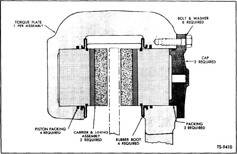
For location and identification of component parts, refer
vided for the bleeding of each set of piston bores by two
to the Brake Head Exploded View, (Figure 1, Page 1). and
bleeder valves, one for each side of the torque plate. A tube
the Crossectional View (Figure 2) shown below.
Fig. 2. Brake Head Cross-sectional View
[2]

