
Fig. 9. Install New Brake Lining
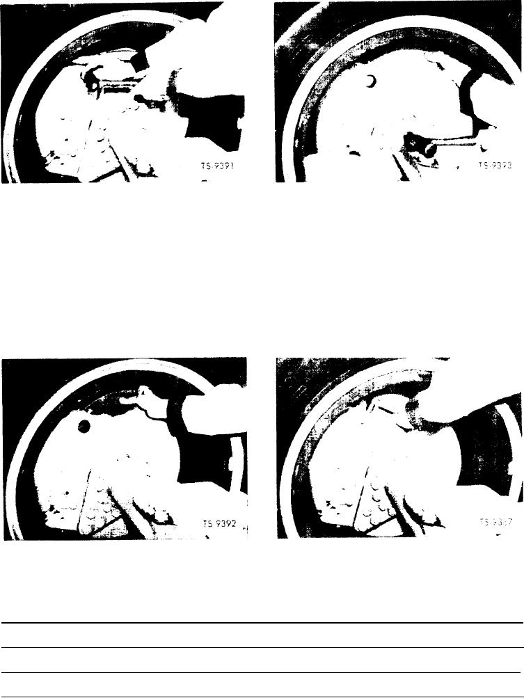
Fig. 7. Drive Second Unlocked Pin Back
along contour of disc and seat against retaining pin as
7. Refer to Figure 8 and remove brake carrier and lining
shown in Figure 9.
assemblies from both sides of disc by rotating lining
along contour of disc.
11. Reinstall retaining pins. A suitable "C" clamp may be
used to farce pins in place.
8. Open bleeder screws on both sides of brake head and
depress all four pistons as far back into brake head as
12. Retighten locking bolts, making sure bolts seat in groove
possible. A small pry bar may be used if required.
in retaining pins. See Figure 10.
9. Close both bleeder screws.
13. Pump brake pedal several times until linings are in con-
tact with disc.
10. Replace carrier and lining assemblies by rotating same
Fig. 10. Tighten locking Salts
Fig. 8. Remove Brake Lining
NOTES
[4]