TM 5-3805-258-24-1
3304 DIRECT INJECTION VEHICULAR ENGINE
SPECIFICATIONS
WITH SCROLL FUEL SYSTEM
CAMSHAFT
NOTE: Put a layer of 5P960 Grease or graphite grease on lobes of
camshaft when installing.
(1)
(2)
(3)
(5)
Width of groove in camshaft for thrust washer
(new) . . . . . . . . . . . . . . . . . . . . . . . . . . . . 4.83 + 0.05 mm (.190 t .002 in.)
Thickness of thrust washer
(new) . . . . . . . . . . . . . . . . . . . . . . . . . . .
4.65 ~ 0.03 mm (.183 * .001 in.)
End play of the camshaft
(new) . . . . . . . . . . . . . . . . . . . . . . . . . . . .
0.18 f 0.08 mm (.007 * .003 in.)
Maximum permissible end play
(worn) . . . . . . . . . . . . . . . . . . . . . . . . . . . . . . . . . . . . . . . . . . . . . . . . . . . . . . 0.64 mm (.025 in.)
Diameter of camshaft bearing surface (journal)
(new) . . . . . . . . . . . . . . . .
58.699 i 0.013 mm (2.3110 * .0005 in.)
Bore in bearing for camshaft
(new) . . . . . . . . . . . . . . . . 58.801 * 0.061 mm (2.3150 t .0024 in.)
Clearance between bearing and bearing surface (journal)
(new) . . . . . . . . . . . . . . . . . . . . . . . . . . . . . .
0.05 to 0.15 mm (.002 to .006 in.)
Maximum permissible clearance between bearing and bearing
surface (journal) (worn) . . . . . . . . . . . . . . . . . . . . . . . . . . . . 0.20 mm (.008 in.)
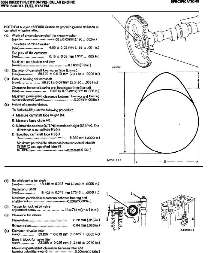
Height of camshaft lobes.
To find lobe lift, use the following procedure:
A. Measure camshaft lobe height (5).
B. Measure base circle (6).
C. Subtract base circle (STEP B) from lobe height (STEP A). The
difference is actual lobe lift (4).
D. Specified camshaft lobe lift (4)
is . . . . . . . . . . . . . . . . . . . . . . . . . . . . . . . . . . . . . . . . . . . . . . . . . . . .
8.382 mm (.3300 in.)
Maximum permissible difference between actual lobe lift
(STEP C) and specified lobe lift
(STEP D) is . . . . . . . . . . . . . . . . . . . . . . . . . . . . . . . . . . . . . . . . 0.25 mm (.010 in.)
(1)
(2)
(3)
(4)
VALVE ROCKER ARMS AND LIFTERS
Bore in bearing for shaft
(new) . . . . . . . . . . . . . . . . . .
18.448 ? 0.013 mm (.7263 f .0005 in.)
Diameter of shaft
(new) . . . . . . . . . . . . . . . . . .
18.402 t 0.013 mm (.7245 * .0005 in.)
Maximum permissible clearance between bearing and
shaft (worn) . . . . . . . . . . . . . . . . . . . . . . . . . . . . . . . . . . . . . . . . . . . . . 0.20 mm (.008 in.)
Torque for locknut on valve
adjustment screw . . . . . . . . . . . . . . . . . . . . . . 28 & 7 N.m (21 t 5 Ib.ft.)
Clearance for valves:
Intake valves . . . . . . . . . . . . . . . . . . . . . . . . . . . . . . . . . . . . . . . . . . . .
0.38 mm (.015 in.)
Exhaust valves . . . . . . . . . . . . . . . . . . . . . . . . . . . . . . . . . . . . . . . .
0.64 mm (.025 in.)
Diameter of valve lifter
(new) . . . . . . . . . . . . . . . .
33.287 * 0.013 mm (1.3105 * .0005 in.)
Bore in block for valve lifter
(new) . . . . . . . . . . . . . . . .
33.388 t 0.025 mm (1.3145 * .0010 in.)
Maximum permissible clearance between lifter and
bore for valve lifter (worn) . . . . . . . . . . . . . . . . . . . . . . . 0.30 mm (.012 in.)
2-8


